Protocol - Heart Valve Function
Description
Measure to assess the structure and function of the valves within the heart to determine the presence of dysfunction.
Specific Instructions
If respondent answers "yes" to question "1," proceed to item "2.0 The Echocardiographic Examination." Performing an echocardiograph provides additional specificity for determining presence of heart valve dysfunction.
Availability
This protocol is freely available; permission not required for use.
Protocol
1. Has a doctor ever told you that you had rheumatic heart disease or heart valve problems?
[ ] 1 Yes
[ ] 0 No
[ ] 9 Dont Know
2.0 THE ECHOCARDIOGRAPHIC EXAMINATION
This section will give an overview of the instrument preparation, patient preparation, and performance standards for the echo examination. The echo technician will record information on the Echo Technician Worksheet.
2.1 Presets on the Instruments
2.1.1 Echo Machines Application Presets
The echo machine features programmable "application" presets to allow customization of preferred image and Doppler settings, and to allow efficient selection of alternate settings if needed, for example, in the case of technically difficult imaging studies. A preset will be defined for the JHS echo study based on typical imaging and Doppler parameters for cardiac ultrasound and on the crucial need for high quality M-mode and 2-D data. This preset is active automatically when the machine is powered up, and it can be re-selected from the keyboard prior to each study. The technician may modify some parameters during the course of a study to optimize data quality but these changes are returned to nominal settings when the JHS "application preset" is selected.
2.1.2 Digital Storage System Protocols
The digital image network will obtain participant name and identification from the technicians entries on the echo machine itself. There will be no individual settings required on the digital system prior to the echo examination.
2.2 Equipment Preparation Prior to Each Study
2.2.1 Echo Machine Preparation
General care instructions are found in the documentation supplied with the machine. Prior to each study the transducer heads should be wiped clean in accordance with the manufacturers instructions. Disposable EKG electrodes are snapped onto the three leads of the EKG cable prior to attaching to the participant. If any machine parameters have been altered by the previous study, reactivate the "application preset" for JHS. The technician should be confident that recording device(s) are ready and properly positioned to record a new study. The technician should fill in the study identification information on the screen and double-check the participant identification before beginning echo study.
2.2.2 Digital Storage System Preparation
Preparation of the digital imaging network may or may not be required depending on how the selected vendor has implemented the interface with the echo machine itself. Once the participant identification is known to both the echo machine and the imaging network, the image acquisition may begin.
2.3 Participant Preparation
The participant should remove all clothing from the waist up and don a clinic gown which will provide access to the chest as needed for imaging.
The technician will measure the participants blood pressure in a comfortable supine position and record it on the imaging systems information screens.
Position the subject in the left lateral position with the head propped up at a slight angle on pillows and a wedge behind him to help maintain this position comfortably. Attach three EKG electrodes as labeled. The "arm" leads (RA and LA) may be placed on the upper chest near the shoulders, and the "left leg" lead (LL) may be placed on the abdomen. The leads should be draped without tension in a way that they will not interfere with the subsequent examination. Check that a clear EKG signal is displayed on the echo machine. The EKG size control on the echo machine is generally best left in the "AUTO" position.
2.4 Imaging Views and Information Sought
This section reviews the standard set of acoustic windows to be used and the data sought from each view. In addition, a list of items to be recorded is given. In general, for each imaging view and mode specified below, the technicians will activate the "record" button to capture images for a period of time that will encompass 10-20 heartbeats of relevant data unless otherwise specified. All recordings will be performed at end-expiration, obviating the need for using a respirometer and adding consistency to the measurement processes.
2.4.1 Parasternal Views
These views are usually performed in the left 3rd or 4th intercostal space adjacent to the sternum.
2.4.1.1 Parasternal Long Axis View
The ultrasonographer attempts to line the beam perpendicular to the interventricular septum and posterior left ventricular wall. Initially, the focus is on obtaining a clear 2-D image of the aortic valve, aortic root, left atrium, right ventricle, left ventricle, and mitral valve. Color Doppler interrogation is performed to assess aortic and mitral regurgitation.
Data recorded in the parasternal long-axis view:
- 2-D imaging
- Color Doppler mitral and aortic valves
2.4.1.2 Right Ventricular Inflow View
In a modification of the parasternal long axis view, the transducer is angled to the subjects right, demonstrating the tricuspid valve anatomy.
Data recorded in the RV inflow view:
- 2-D imaging
- Color Doppler tricuspid valve
2.4.1.3 Parasternal Short Axis View
From the long axis position, the transducer is rotated clockwise 90-degrees to obtain the short axis view. The exam begins at the left ventricular (papillary muscle) level to demonstrate ventricular anatomy and wall motion.
Images are recorded at the mitral valve level to show valve anatomy and motion.
Images are recorded at the aortic valve level to show valve anatomy and motion. Color Doppler is performed at the pulmonary, aortic, and (if adequately visualized) tricuspid valves.
The technician returns to the aortic valve level to perform M-mode recording of the aortic valve and left atrium. M-mode examination is performed at the papillary level taking care to orient the transducer for a view perpendicular to the long axis of the ventricle (creating a circular, rather than oblong, shape to the tomographic image). The M-mode cursor is positioned through the center of the chamber and gain settings are adjusted to optimize the boundary detection of the walls of the interventricular septum and posterior wall. While optimizing M-mode angle and image quality the echo machine display is a split screen showing both M-mode and a miniaturized 2-D image. When the data are optimal, the M-mode display is changed to full screen. The FREEZE button is pressed after a full sweep is displayed in the larger format.
The same procedure is carried out for the images at the aortic valve level, described above.
NOTE: If the technician feels that the image data are technically better from the parasternal long-axis view, then that view will be used for M-mode data, positioning the cursor just beyond the mitral leaflet tips and carefully selecting the image plane to coincide with the long axis of the left ventricle. The M-mode data at the aortic valve level may also be obtained from the parasternal long-axis view if image quality is felt to be significantly better than short axis.
Data recorded in the parasternal short axis views:
- 2-D at aortic, mitral, and pulmonary valves
- Color Doppler of valves at aortic level
- 2-D images of LV at papillary level
- M-Mode of LV at papillary level
- M-Mode of Aortic valve and LA
2.4.2 Apical Views
These views are performed in the interspace where the ventricular apex is felt, usually in the left 5th or 6th interspace in the between the midclavicular and anterior axillary lines.
2.4.2.1 Apical 4 Chamber View
The technician strives to achieve an imaging plane directly over the left ventricular apex, parallel to the interventricular septum, and rotated in a manner to show all 4 chambers and both the mitral and tricuspid valves simultaneously.
For efficiency in the protocol, the technician will perform pulsed wave spectral Doppler examinations first.
For mitral inflow data, the range gate is placed near the tips of the mitral leaflets with small adjustments in angle to obtain maximum flow velocity data with a narrow spectral dispersion. After 2-D directed placement of the range gate cursor using the split screen (Doppler and miniature 2-D) mode, a full screen sweep of spectral Doppler is frozen on the screen. A Doppler range gate is placed in the pulmonary vein just posterior to the left atrium, and spectral Doppler recordings are made in the same manner as mitral inflow recordings.
For aortic outflow data, the transducer is tipped to image slightly anterior from the 4 chamber view to show the aortic valve and outflow tract (the "5 chamber" view). The range gate cursor is placed in the left ventricular outflow tract about 0.5 to 1 cm proximal to the aortic valve, again trying to demonstrate a pattern of narrow spectral dispersion and a well-defined velocity profile. Data are recorded as for mitral above. The Doppler mode is then switched to CW (continuous wave) and the interrogating beam directed through the aortic valve to measure peak velocity.
Next the focus in on clear 2-D images of the 4 chambers and AV valves. This view is recorded with particular attention to definition of LV wall boundaries and wall motion.
Data recorded in the apical 4 chamber view:
- Pulsed Doppler of mitral inflow
- Pulsed Doppler/CW Doppler of aortic outflow ("5 chamber view")
- 2-D images of 4 chamber view
- Color Doppler (mitral, aortic, tricuspid)
- Pulsed Doppler of pulmonary vein flow
2.4.2.2 Apical 2 Chamber and Long Axis Views
From the 4 chamber view, the transducer is rotated along its imaging axis 90 degrees counterclockwise to show the left ventricle and atrium from the apex (the 2 chamber view). This view is recorded and the 2-D images are captured on the digital system with particular attention to definition of LV wall boundaries and wall motion. The transducer is rotated slightly to simultaneously image the mitral and aortic valves (the apical long axis view) and color flow Doppler data is recorded.
Data recorded in the apical 2-chamber and long axis:
- 2-D image of 2-chamber view
- Color Doppler of mitral/aortic in long axis
2.4.3 Supplementary Views
With the important priority of measuring LV wall and chamber dimensions, inability to obtain useable images from other acoustic windows (especially parasternal) should prompt the technician to image from the subcostal view. Both a 4 chamber view and a short axis of the LV at the papillary level should be attempted. Recognition by the technician of significant abnormalities should prompt further examination which may require additional views. For example, a suggestion of aortic root dissection should prompt examination from the suprasternal notch. Sometimes supplementary Doppler interrogation from standard views is required, such as with the recognition of valvular aortic stenosis where continuous wave Doppler (CW) should be carefully employed to measure peak flow velocity through the valve.
2.5 Completing the Study
2.5.1 Completing Data Storage
The final procedure for the echo examination is to indicate the completion of the study [by keyboard command on the echo machine] so that the images can be transmitted to the network server and subsequently to the digital archive.
2.5.2 Completing the Participant Encounter
During the file save operation is a convenient time to disconnect the EKG cable and remove the electrode pads. Provide the participant with a towel to remove any residual ultrasound gel while he/she gets dressed.
2.6 Transmittal of Data to the Echo Reading Center
At the completion of the days studies, any written worksheets and logs are copied and packaged together for pickup by the ERC where the data will be analyzed. It is anticipated that studies will be delivered on a daily basis. The studies will be logged in at the Reading Center using the information on the technician worksheets. The echo study itself is stored on the image server accessible to the ERC over the imaging systems network connections. Each studys progress through the reading and data entry processes will be noted in the logs of the reading center.
Diagnostic Criteria:

Personnel and Training Required
Cardiac sonographers with strong experience in clinical imaging are recommended. The sonographer should undergo training to perform echocardiography examinations per the study echo exam protocol.
Equipment Needs
Echocardiography machine, ultrasound gel
Requirements
| Requirement Category | Required |
|---|---|
| Major equipment | Yes |
| Specialized training | Yes |
| Specialized requirements for biospecimen collection | No |
| Average time of greater than 15 minutes in an unaffected individual | No |
Mode of Administration
Interviewer-administered question, Clinical measurement
Lifestage
Adult
Participants
Cardiovascular Health Study (CHS): ≥65 years old
Jackson Heart Study (JHS): ages 35–84 years olf
Note: This protocol has been reliably used with ages 35–84 years old. However, the Working Group suggests the same methodology can be used for other ages.
Selection Rationale
The personal history protocol from the Cardiovascular Health Study (CHS) was selected to determine the history of heart valve problems. For additional specificity, an echocardiograph can be performed. The combination of 2-D and Doppler echo is the single most useful diagnostic test to determine heart valve function. The Jackson Heart Studys (JHSs) Echocardiographic Examination protocol provides reliable and validated instructions for how to conduct a 2-D and Doppler echocardiographic examination.
Language
Chinese, English, Other languages available at source
Standards
| Standard | Name | ID | Source |
|---|---|---|---|
| Logical Observation Identifiers Names and Codes (LOINC) | PhenX - heart valve func protocol | 62394-2 | LOINC |
| Human Phenotype Ontology | Abnormal heart valve physiology | HP:0031653 | HPO |
| Human Phenotype Ontology | Abnormal heart valve morphology | HP:0001654 | HPO |
| caDSR Form | PhenX PX040501 - Heart Valve Function | 5822572 | caDSR Form |
Derived Variables
None
Process and Review
Not applicable.
Protocol Name from Source
Cardiovascular Health Study (CHS), Baseline Medical History Questionnaire & Framingham Heart Study (FHS)
Source
U.S. Department of Health and Human Services. National Institutes of Health. National Heart, Lung and Blood Institute. Cardiovascular Health Study (CHS). Baseline Medical History Questionnaire. Page 5. Question 6 (source for question 1 in Protocol Text).
U.S. Department of Health and Human Services. National Institutes of Health. National Heart, Lung and Blood Institute, National Center on Minority Health and Health Disparities, and the National Institute of Biomedical Imaging and Bioengineering. Jackson Heart Study (JHS). Manual 6. Echocardiography. Visit 1. Version 1.0. February 15, 2001 (source for question 2.0 in Protocol Text).
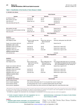
Bonow, R. O, Carabello, B. A., Chatterjee, K., de Leon, A. C., Jr., Faxon, D. P., Freed, M. D., Gaasch, W. H., Lyttle, B. W., Nishimura, R. A., OGara, P. T., ORourke, R. A., Otto, C. M., Shah, P. M., & Shanewise, J. S. (2008). 2008 Focused update incorporated into the ACC/AHA 2006 guidelines for the management of patients with valvular heart disease: A report of the American College of Cardiology/American Heart Association Task Force on Practice Guidelines (writing committee to revise the 1998 Guidelines for the Management of Patients With Valvular Heart Disease). Endorsed by the Society of Cardiovascular Anesthesiologists, Society for Cardiovascular Angiography and Interventions, and Society of Thoracic Surgeons. Journal of American College of Cardiology, 52, e1–e142. Retrieved July 16, 2009, from http://content.onlinejacc.org/cgi/content/full/52/13/e1 (source for Diagnostic Criteria).
General References
Ives, D. G., Fitzpatrick, A. L., Bild, D. E., Psaty, B. M., Kuller, L. H., Crowley, P. M., Cruise, R. G., & Theroux, S. (1995). Surveillance and ascertainment of cardiovascular events. The Cardiovascular Health Study. Annals of Epidemiology, 5, 278–285.
Psaty, B. M., Kuller, L. H., Bild, D., Burke, G. L., Kittner, S. J., Mittelmark, M., Price, T. R., Rautaharju, P. M., & Robbins, J. (1995). Methods of assessing prevalent cardiovascular disease in the Cardiovascular Health Study. Annals of Epidemiology, 5(4), 270–277.
Protocol ID
40501
Variables
Export Variables| Variable Name | Variable ID | Variable Description | dbGaP Mapping | |
|---|---|---|---|---|
| PX040501_ECG_Examination_Date | ||||
| PX040501020100 | Date of Electrocardiogram (ECG) Examination more | Variable Mapping | ||
| PX040501_ECG_Image_ID | ||||
| PX040501020200 | Electrocardiogram Trace/Image ID. | N/A | ||
| PX040501_Ever_Have_Heart_Valve_Problem | ||||
| PX040501010000 | Has a doctor ever told you that you had more | Variable Mapping | ||
Measure Name
Heart Valve Function
Release Date
September 9, 2009
Definition
Measure to assess the structure and function of the heart valves.
Purpose
To determine the function of the heart valves in order to assess risk factors for stenosis or insufficiency of the mitral, aortic, pulmonary or tricuspid valves of the heart.
Keywords
Cardiovascular, heart valve function, mitral valve, aortic valve, pulmonary valve, tricuspid valve, echocardiographic examination, echocardiogram, Jackson Heart Study, Cardiovascular Health Study, CHS, Doppler echo, Doppler echocardiogram, valvular dysfunction, valvular heart disease, heart valve, echo, rheumatic fever, heart murmur, mitral valve prolapse, aortic stenosis
Measure Protocols
| Protocol ID | Protocol Name |
|---|---|
| 40501 | Heart Valve Function |